OpenGL Texturing has been re-invented multiple times, with different hardware implementations each time. As a developer, you need to be comfortable with all of them.
UPDATE: there is now a branch on GitHub specifically for the source code from this post: GLKExtended Part 5. That branch also has the code separated into a Static Library and a DemoApp, so you can easily re-use the code in your own projects
The newest (and preferred) system is provided by the Fragment Shader itself. People often don’t bother to name it, but technically it’s “procedural texturing”. This is fast, extremely configurable, and has potentially infinite resolution. It’s the most general-purpose scheme (in GL ES, the other texturing systems are partly built on top of it). But if you google for it, you’ll get hits almost exclusively on the hardcore “niche-within-a-niche” of advanced procedural techniques.
For instance, browse the awesome ShaderToy.com. ShaderToy demos nearly always use procedural texturing to some extent. The most impressive ones use an extreme form that eschews polygons completely, and converts the whole of OpenGL into a pseudo-ray-tracer. I’m not going to explain it, but if you’re interested, ShaderToy’s author wrote an article that explains the basics of that approach.
The oldest system is “texture-mapping”, that uses raw images (e.g. PNG – but could be simple byte-arrays of data) and wraps them onto a surface. OpenGL tutorials often start with this because it’s the one GL coders have used for longest, even though it’s harder to use and less powerful.
The first two posts will cover different approaches to Texturing, the third one will cover simple special effects:
- Part 5. Textures 1 of 3: Texturing Triangles using Shaders
- Part 6. TBD: Textures 2 of 3: Texture-Mapping Triangles using Bitmaps
- Part 7. TBD: Textures 3 of 3: Animating Textures using Uniforms
But before we go further, we need to understand where Texturing comes from…
Resolution
Whenever you draw an image to screen in 2D, artists and programmers have to agree on two things. 3D has some extra worries, but in 2D it’s simply:
- Image format (PNG? JPG? etc)
- Image resolution (320×240? 100×100? 32×32? etc)
Working together, there are two techniques you can use to define resolution:
- Start from “what percentage of screen size (%) I want”, and work backwards
- Start from “what image-size I want (pixels, voxels)”, and work forwards
You choose one approach or the other based on what the app is doing with the image. If the image is a background, you’ll want the former: “100% of the width and height of the screen / window”.
But if the image is a sprite (e.g. an ememy spaceship), you usually want the latter: a fixed pixel size. Of course, this causes larger monitors to show more of the game-area. Usually this is a desirable side-effect: Players bought bigger screens so they would see more!
Programmers can stretch/shrink images if they’re the wrong size – but that causes blurring and pixellation (even when the image is larger than needed).
In 3D … it’s a little more complicated.
Resolution with changing dimensions
The 2D case moves “2D data” (image) to “2D output” (screen). The pixels in an image are not the same thing as pixels on a screen.
This is difficult to appreciate – after all, they’re both called “pixels”, which doesn’t help. And they seem similar. But image pixels might be a single number (greyscale) or 3 numbers (r/g/b), or 4 numbers (r/g/b/ALPHA), etc … whereas screen pixels are usually 4 separate lights (e.g. r/g/b/r – yes, two reds), and cannot have ALPHA (although transparent monitors exist, they’re very rare).
The 3D case still has to use “2D output”, but now has “3D data”. We have two options, roughly corresponding to the two approaches in 2D.
Resolution in 3D, technique 1: “…and work backwards”
Similar to the 2D background-image, we start with the output/screen resolution, and construct input/data that matches it 1:1.
If we want a razor-sharp image that covers the whole screen, and we want to draw whatever we want, we need one vertex per pixel. To make it easy, we’ll make a giant sheet of “virtual paper” facing the camera, with all vertices an equal distance from the camera, but spread out on a grid that’s the same resolution (in vertices) as the screen (in pixels).
This might seem a bit strange, but it works. And it has valid uses – it does not use Fragment Shaders or texture-files at all (which is sometimes desirable) – but they’re uncommon/rare.
From a programming perspective, with a fixed camera, and fixed 3D scene (little or nothing moves) this is easy to set up. We calculate the positions needed, we find out what colours our 3D model / scene has at those points, and create the vertices.
Desktop GPU’s can shift enough vertices to make this work great. Mobile GPU’s are suprisingly fast with verts – but Apple’s devices have insanely high-resolution screens (my iPad3 has more pixels than my 27″ desktop monitor), and over-stretch the GPU here (for now).
e.g. For an iPad2, you have approximately 1.5 million pixels to colour. The iPad2 can shift 60+ million vertices per second, so we could hit 60 FPS if we did no other graphics work. Switch up to the iPad3 – 3 million verts, and only 2x the processing power – and you can’t even manage that.
Resolution in 3D, technique 2: “…and work forwards”
There are two projections in 3D->2D rendering: Orthogonal (used e.g. by Architects to draw views of buildings) and Perspective (used e.g. by FPS games to give a 3D visual effect).
In Orthogonal rendering, you can calculate in advance how many “units in 3D” will map to “1 unit in pixels” – and the number doesn’t change as you move the camera around.
But in Perspective rendering, objects change their size based on distance from the camera …
… and so it’s impossible to tell an artist “use this many vertices – no more, no fewer! – to make your 3D object render sharp at all times, with no wastage”.
Ultimately, the only way to work out how many vertices are needed to cover the pixels is to render the 3D image to 2D, and measure how many pixels you ended up colouring-in
i.e. we’d have to do the full work of rendering the scene to screen … just so we can find out what resolution the incoming assets have to be. Before we can create the assets? Argh. This sounds like a chicken-and-egg scenario!
But this is exactly what fragment-shaders do / allow us to do…
Texturing a flat surface
How do we choose “which pixel gets which colour”?
We don’t. Instead we get to choose “which colour each pixel gets”.
The trick that OpenGL uses is:
- take a fixed description of a surface, although the surface itself can move (e.g. a 3D object made of triangles)
- use a variable number of internal/low-level rendering calls from frame-to-frame
NB: these “rendering calls” are simply an abstract concept to help me explain what’s happening. These are nothing to do with Draw calls!
For a triangle, on each Draw call:
- The Vertex shader is always called three times: once per vertex.
- The Fragment shader is called anywhere from “zero” up to “(width of screen) x (height of screen)” times: it depends how many pixels the triangle covers
In previous parts we ignored this distinction: we rendered the whole triangle one colour. There was no way for us to notice that the Fragment Shader was being invoked many more times than the Vertex Shader.
To choose a colour for the current pixel, we need some extra information passed-in to our Fragment Shader…
Variables in Shader Programs
There are four types of variable you can use in shader programs:
- Local variables, that help you organize the code (no other purpose!) — these act like normal variables
- Attributes (vertex only) — arbitrary data that the vertex shader can READ
- Uniforms — like Attributes, but they have the same value for every vertex in a Draw call
- Varyings — data passed from Vertex Shader to Fragment Shader: vertex shader WRITES, and Fragment shader READS
We’ve already used Attributes, and Local variables are self-evident. We’ll skip those two.
Uniforms are required for old-style Texturing (texture-mapping), but optional for procedural Texturing, so we’ll leave them to a later post.
What’s left?
Shader Variables: Varyings
In a vertex shader, Attributes and Uniforms both appear to have a value “per vertex” (with the Uniform, it’s always the same value, at least during a single Draw call).
Note: In desktop GL, “Attributes, Uniforms and Varyings” have been renamed/replaced with a simpler system of labelling each variable as “in” (you read from it – e.g. Attributes and Uniforms), “inout” (both reading and writing – i.e. Varyings), etc. Any code with in/inout/etc needs some rewriting to make it work in GL ES.
The vertex shader then writes all its output as “varyings”. This is where the texturing magic comes in. You do this:
- calculate a value for each varying, using the Attributes of this Vertex
- write that value to the varying (e.g. “0.0” for vertex-1, “1.0” for v-2, and “2.0” for v-3)
…but OpenGL does this:
- calculate a value for each varying, using the Attributes of this Vertex
- write that value to the varying (e.g. “0.0” for v-1, “1.0” for v-2, and “2.0” for v-3)
- …
- use the fact this is a “GL_TRIANGLES” draw call to generate a triangle from v1, v2, v3
- work out which pixels on-screen this triangle will cover
- for each pixel:
- work out the distance of that pixel to each of v-1, v-2, v-3
- take the weighted average of the values of each varying
- pass that “weighted” value of the varying into the Fragment Shader
e.g. if you give a triangle’s vertices colours of “red”, “green”, and “blue”, OpenGL will draw a triangle that looks like a colour-chart: a smooth gradient between the three corners. Here’s an example:
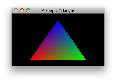
…OpenGL is working out each pixel it needs to draw, then estimating a “simulated” set of vertex-attributes for each varying (as if each pixel had a vertex at that point).
Technically, OpenGL calculates the texture as a series of gradients, and then lets you filter those gradients to produce the output texture.
If we didn’t have Fragment Shaders, we could only fill triangles with gradients or solid colours. But the fragment shader is executable source code, allowing us to post-process the varyings, and choose arbitrary colours for each pixel.
Texturing via Varyings
That point above is very important: the way Fragment Shaders work is to use Gradients that run across the surface of the triangle. This means that if you want – for instance – to use a texture that’s a single “line” gradient, you only need one varying on your three vertices.
But if you want – for instance – your texture to be circular, you need to give the Fragment Shader a circular gradient to work with. This requires two varyings per vertex (A line is 1-dimensional, but a circle is 2 dimensional).
(Look back at the coloured triangle I showed above. The code for this assigned an RGB value to each corner/vertex. Technically, that’s three Varyings per vertex – a “red” (from 0..1), a “green”, and a “blue”. It generated three independent line-gradients (along the edges), and OpenGL smoothly blurred them together where they overlapped towards the center.)
A varying can only vary based on the input variables to the Vertex Shader.
…and in GL ES 2, only “Attributes” differ from Vertex to Vertex.
Generate a Varying from Attributes
To make an interesting/meaningful varying, we’ll need at least one corresponding Attribute (you could use multiple Attributes per Varying, but in the simple case: one is enough). You need different names for the “attribute” and the “varying” so that the Vertex shader can read the former and write the latter.
When you’re only using one Attribute to generate your Varying, standard naming practice is to prefix them to make it clear which is which. e.g. a variable called “myVariable”:
- Attribute: “attribute mediump float a_myVariable”
- Varying: “varying mediump float v_myVariable”
We’re going to make something that varies in 2D across the surface of the triangle (1D is boring). We’ll use a virtual x and a virtual y. They don’t have to be separate floats – we can use a single GLKVector2 (a.k.a. “vec2” in shader source code). We’ll also show that Vertex Shaders don’t simply “copy” varyings but instead calculate them on the fly.
Don’t forget the nasty Xcode4 and Xcode5 bug: whenever you add a new Shader file, Apple will “remove” your shader from the build. Each time, you have to go into Build Settings and drag/drop it from “compile sources” to “copy bundle resources”
VertexPositionUnprojected.vsh:
[c]
attribute vec4 position;
attribute vec2 a_virtualXY;
varying mediump vec2 v_virtualXY;
void main()
{
v_virtualXY = 3.1415926 * (2.0 * virtualXY) – 3.1415926;
gl_Position = position;
}
[/c]
… we’ll define our Attributes as running from 0 … 1, and this Vertex shader converts that to -PI to +PI.
Then, in the Fragment Shader, we’ll use sin and cos on those values, to generate RGB values across the texture. This shows how you can decouple your Fragment Shader calculation from your input Attributes, which often makes coding and prototyping less painful. NB: if your Shaders are long and complex, you’ll want to avoid this (to squeeze out more performance), but most shaders are simple enough that it doesn’t matter.
FragmentXYParameterized.fsh:
[c]
varying mediump vec2 v_virtualXY;
void main()
{
/** Let’s do something interesting with the virtual X, Y we’ve been given */
mediump float red, green, blue; // some Local variables. Inefficient, but makes code easier to read
red = green = blue = sin( v_virtualXY.x ) + sin( v_virtualXY.y ); // use both X and Y to make a texture that’s 2D
blue *= cos( v_virtualXY.y ); // do something different with BLUE just for fun
gl_FragColor = vec4( red, green, blue, 1.0 );
}
[/c]
Modifying the app to use the new shaders
We need to use the new Fragment Shader, and upload data for the new Attribute to the GPU:
ViewController.m:
[objc]
GLK2ShaderProgram* sharedProgramForBlueTriangles = [GLK2ShaderProgram shaderProgramFromVertexFilename:@"VertexPositionUnprojected" fragmentFilename:@"FragmentXYParameterized"];
…
GLKVector2 attributesVirtualXY [3] =
{
GLKVector2Make( 0, 0 ), // note: we vary the virtual x and y as if they were x,y co-ords on a right-angle triangle
GLKVector2Make( 0, 1 ),
GLKVector2Make( 1, 0 )
};
…
for( int i=0; i<4; i++ )
{
…
draw1Triangle.VAO = [[GLK2VertexArrayObject new] autorelease];
…
GLK2Attribute* attXY = [draw1Triangle.shaderProgram attributeNamed:@"a_virtualXY"];
[draw1Triangle.VAO addVBOForAttribute:attXY filledWithData:attributesVirtualXY bytesPerArrayElement:sizeof(GLKVector3) arrayLength:draw1Triangle.numVerticesToDraw];
…
[/objc]
The net result is four triangles with a slightly weird pattern. If you’re observant, you’ll notice that sin() and cos() generate numbers in the range -1 to 1 – while the minimum value for red, green, or blue components is 0. Hence a largely black area.

Congratulations! Your first textured triangle!
Did this post help you?
If you’re finding these OpenGL ES tutorials useful, enter your email, and I’ll let you know the next time I post one. I’ll also send you some info about my current personal-project, a 3D game/app which uses these techniques:
End of part 5
Now’s a good time to play with the fragment shader. Try editing the Fragment Shader so that it converts the output (-1..1) into output (0..1).
Or: try out different functions for red, green, and blue. If you google for “random numbers in fragment shader” you can even find some (very slow, big performance hit) functions that give you a (seemingly) random number, and you can apply a white-noise style texture.
Have fun with it.
Next post: Part 6: Textures 2 of 3: Texture Mapping